

General Cable Assembly Information
Microwave/RF coaxial cable assembly is done by installing the connectors on a RF coaxial cable via special technology, which is served as a transmission line. Specific requirements must be carefully considered for the proper selection of cable assemblies, including, but not limited to the cable and connector constructions, materials, frequency range, VSWR, insertion loss, mechanical requirements, and any environmental or application restrictions. The design engineering should carefully and precisely evaluate electrical, mechanical and environmental factors in order to optimize the solution for a specific application.
General Characteristics of Cable Assembly
Impedance (Z0)
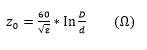
“Characteristic impedance” is generally implied when speaking of the impedance of a cable, connector, or cable assembly. Maximum power transfer and minimum signal reflection occurs when the characteristic impedance of a cable assembly matches that of the other components in the system. If the impedances all match, losses are due only to the attenuation of the transmission line; otherwise there will be additional reflection losses. The characteristic impedance (Zo) is directly related to the ratio of the ratio of the inner and outer conductor diameters, and inversely related to the dielectric constant of the core material (ε). Due to the “skin effect” of RF energy transfer, the important dimensions are the outer diameter of the center conductor, d, and the inner diameter of the outer conductor, D.
VSWR
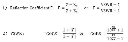
Reflections back toward the input end of a cable assembly are caused by variations in impedance along the length of a cable assembly and can cause energy loss by interaction with incident wave.
Voltage Standing Wave Ratio is the ratio of the maximum to the minimum voltage of a standing wave (which is the instantaneous sum of incident and reflected waves).
Then the VSWR is defined by the following formula:
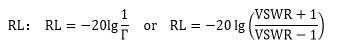
Return Loss
Return loss is the ratio (expressed in dB) of the power of the original signal vs. the power of the reflected signal. Thus, return loss indicates the relative size of the reflected signal and, therefore, how perfectly or imperfectly the transmission line is terminated. The equivalent parameter is either the reflection coefficient or VSWR. Return loss can be calculated by reflection coefficient:
Attenuation (Insertion Loss)
The total insertion loss of cable assembly is comprised of the loss of connectors, cable and mismatch loss.
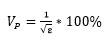
Velocity of Propagation
Velocity of propagation is the speed of the transmitted signal as compared to the speed of light and is inversely proportional to the square root of the dielectric constant. Material with a lower dielectric constant will yield a higher velocity of propagation.
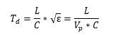
Delay Time
Delay time is the duration of time that a signal takes from entrance to exit in a coaxial line. The delay time is independent of the frequency and is a function of the dielectric constant and physical length of the transmission line, usually expressed in nanoseconds (10 -9 seconds) per foot.
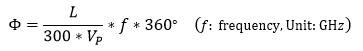
Phase
Applications such as antenna may require cable assemblies to have intended velocity of propagation and transmission time, and this is determined by a specific electrical length of cable assembly instead of physical length. Phase is used calculate the electrical length.
Phase Matching
Phase matching denotes two or more cable assemblies with the same phase length, or electrical length. Phase matching can be absolute, as compared to a predetermined value, or relative, where the assemblies are matched to each other.
Phase Stability over Flexure
Phase stability over flexure is the phase shift by bending the cable, it can be significantly affected by the bending method and bend radius, which should be taken into account when the degree of change is a concern.
Phase Stability over Temperature
The electrical length for a given frequency will "shift" as a result of environmental changes. The degree of change is based on mechanical stresses, connector torque and thermal conditions.
The degree of phase shift as a result of temperature variation can be calculated by using the following formula:
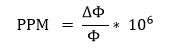
ΔΦ —— Phase change value in degree
Φ —— Electrical length of cable assembly in degree
PPM —— Phase changed part per million
Phase Tracking
Phase tracking is the ability of multiple cable assemblies to closely reproduce their phase characteristics relative to each other over a range of temperature, flexure, or both. Phase tracking is essentially a measure of the assemblies' mechanical consistency. Thermal conditioning of coaxial cable may improve tracking characteristics.
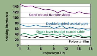
Shielding Effectiveness
The shielding efficiency refers to the ratio of the radio frequency energy incident on one side of the shielding layer to the radio frequency energy transmitted to the other side.
The shielding efficiency is a parameter to measure the anti-interference ability of the coaxial cable, and it is also an important parameter to measure the anti-leakage of the coaxial cable. If the cable is not well shielded, the transmission signal will not only be cross-talked by external clutter, which will affect the signal quality, but will also leak out and interfere with other signals. The higher the shielding efficiency, the better the cable shielding performance.
The shielding layer of radio frequency coaxial cable has various forms. The simplest and most effective shielding layer is the outer conductor of a semi-rigid and threaded coaxial cable, which has a shielding efficiency of over 140dB at frequencies from 1 to 18GHz. There are four common types of shielding layers for flexible radio frequency coaxial cables, the first type is the most common braided round wire shielding layer, the second type is braided flat wire usually silver-plated wire, this type of shielding layer has a strong structure, and the third type is spiral Winding flat wire, the fourth type is to use hardened polymer (polyester film, polyimide or polyester) spiral winding.
Average Power Handling
The cable attenuation generates heat between the center and outer conductor. Power handling capability is reflected in cable capability of withstanding the heat. Power handling is affected by two main factors, one is cable max operation temperature, and another is cable attenuation. Power handling will be higher with better cable attenuation and smaller heat. Under the same conditions, power handling will be higher with higher operation temperature the cable can withstand.
Average power handling is greatly affected by altitude, temperature and VSWR. Average power handling reduces by increase of altitude, temperature and VSWR. Their respective impacts on power handling can be checked by Table 1, Table 2 and Table 3.
Table 1 Reduction Coefficient of Power Handling Influenced by Altitude
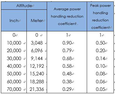
Table 2 Reduction Coefficient of Power Handling Influenced by Temperature
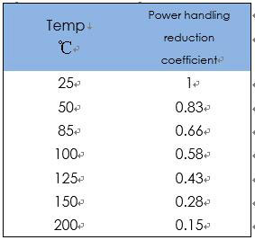
Table 3 Reduction Coefficient of Power Handling Influenced by VSWR
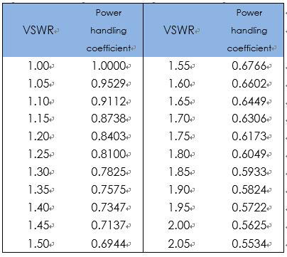
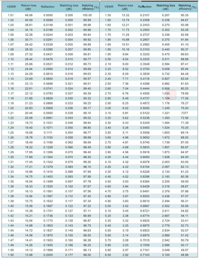
Table 4 VSWR, Return Loss, Matching Loss and Matching Efficiency
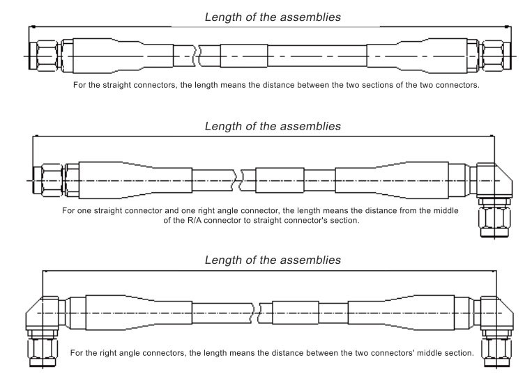
Length of the Assemblies